Search This Blog

Showing posts with label Handyman. Show all posts

Sunday, February 20, 2022

DIY Protective Covers for Continuous Glucose Monitoring (CGM) Sensors


19 February 2022

About 1 in 10 people will have diabetes. This number of diabetes is expected to double in future years.  It is a serious disease that will cause death if it is not properly managed and controlled.  The disease is more commonly found in aged people.   People get diabetes when their blood glucose is too high.  This glucose in the blood is commonly referred to as blood sugar, 

This article will not go into details about controlling and managing blood sugar as there are lots of good articles written about this on the net.   I just want to share about how to DIY a  cover for the Continuous Glucose Monitoring (CGM) Sensors when one happens to wear one.

What is Continuous Glucose Monitoring (CGM)?

There are generally 2 common types of methods to measure the level of blood sugar at home.  One of them is by using a glucose meter with a special test strip;  


the other is by using a special sensor that has to be planted on our body.   


The former is most commonly found at home and have been used for years.   The latter is only available in recent years.  It is by far the most effective way to control and manage the blood sugar in our bodies.  More details about CGM can be found here and elsewhere on the net.   This article will only talk about how to best secure and how to DIY a cover for the  CGM Sensor when it is installed on our body.

Why the need to secure the Sensor?

Usually,  the sensors are provided with means to secure the sensor to our body as one can see in the above picture,  But it does not look really very secure.  It is not that it will fall off that easily;  it is just the feeling of most people who wear them that the sensor could just "shear off" when it hit against something like a door jamb.  Besides,  there is always this sensation of arm-sore that will not go away even after days of wearing the sensor.  This could be because the needle of the sensor could be moving around when one is flexing the arms.  

As such,  one can find a lot of companies selling specially made covers or patches to secure these sensors.  They are not cheap either.


How to DIY the Cover?

There is actually no requirement specified by the manufacturer nor there are any standards available for the design of the sensor cover.   It is generally felt that the cover should have the prerequisites:

a)  It is waterproof;

b)  It must have a strong adhesive to stick firmly.  Easily replaced.

c)  It must not cause skin occlusion 

It must be waterproof so that water will not soak the sensor or its adhesive base when one is taking a bath.  It must have a strong adhesive itself to stick firmly to the skin & easily replaced.    Most important of all,  it must not cause skin occlusion which will often cause skin irritation,  leading to skin rashes or inflammation.  

Searching around,  we found the 3M micropore tape or similar most suitable for the DIY as it fit the 3 prerequisites.  The 3 M tape comes in 4 sizes,  the 3",  the 2",  the 1" and the 1/2".  The most common one found in the self is the 2",  the 1" and the 1/2";  but,  the most suitable one for use as a cover for the sensor is the 3" type.    

How to Use the Smaller size 3M Tape?

The only way is to join the pieces together using the following step by step.  In this case,  the most suitable one is the 1" type.

1)  Cut 3 pieces of 1" tape;  each tape is best to be roughly about 3.5 in length;

2)  Laid the tape on the glass.  In this example,  a mobile phone was used;


3)  Lightly place the 3 pieces of tape,  overlapping the edges as shown attached.   Apply some pressure over the overlapping edges to stick the pieces together;


4)  After that,  remove the tape;

5)  Cut a small round piece of plastic using a small bottle as the template as shown as stick the round piece right in the centre.  the plastic round piece should be larger than the adhesive of the CGM sensor.  This is to ensure the tape will not stick to the sensor and the adhesive and the tape can be easily replaced if necessary;


6)  Trim the DIY sensor cover and place the cover over the sensor as shown.


Thursday, February 3, 2022

How Best to Test & Calibrate a Blood Pressure Meter?

3 February 2022

A blood pressure meter is a common household item nowadays.  This is especially so when there are elderly people in the house.  

In the old day,  we used to have a mercury type of pressure meter which they called "sphygmomanometer".


Today,  most of us will use an electronic type of blood pressure meter as shown below
The good old mercury type of pressure meters are still being used by a lot of medical personnel because it is still the most reliable and accurate pressure meter around; whereas, electronic meters will often need regular calibration and routine checking.

This article will show how one can accurately check the accuracy of an electronic meter.


What's Needed?


How to Connect up?

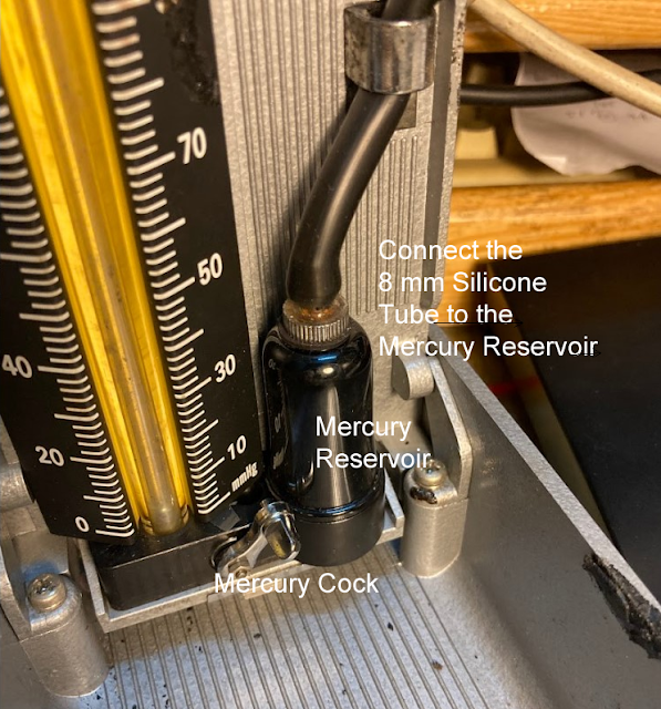
 1.  Connect 8-mm Silicone Tube to the mercury reservoir as shown


2.  Connection the 8-mm tube to the T-Joint


Testing 

As shown in the video,   this Omron Blood Pressure BP742 meter under test has an accuracy of about +4 mm Hg or 3% of reading @ 131 mm Hg.  it is slightly off the manufacturer's limits of +- 3 mm Hg or 2% reading.  However, it has an accuracy of -1 mm Hg or -1% of reading @ 100 mm Hg which is better than the manufacturer's limits.

Diastolic &  Systolic Pressure Readings

To complete the test,  one should also place a stethoscope underneath the handcuff to listen to the heartbeats to check the accuracy of the systolic and diastolic pressure..  

During the working process,  one can hear the meter pumping up the pressure to the handcuff and the heartbeat sounds through the stethoscope as the pressure is building up.  When the pressure goes higher than a certain set of systolic pressure,   the meter will stop pumping.  This is when one could not hear any heartbeats.  Thereafter,  the meter will slowly release the pressure and the pressure readings will drop.  Note down the reading when one first hears a heartbeat. This is systolic pressure.  With further pressure drop,  note the reading when one no longer hear the heartbeat sounds. This is your diastolic pressure.  Compare this two readings with the readings recorded by the meter.  They should be within +-3%.

Calibration

Unfortunately,  there is no adjustment allowed in this Omron Blood Pressure BP742 meter as shown in the following picture.  It would appear the calibration has to be carried out by using some kind of software and this can be done only by the manufacturer as explained by the author of this article...


How Much is a Sphygmomanometer?

The market is selling a Sphygmomanometer at a price of around SGD 40/= to about SGD 300/=.


Monday, January 24, 2022

Repairing Philips Electric Shaver Model C644


24 January 2022

This Phillips Shaver was found not working.   The blade will move but if one starts to cut the hairs,  the cutting blade will stop moving.  One can still hear the motor spinning in the background.   If one removes the blade from the unit,  one can see that the blade rotator will spin but it will stop if one tries to use one's finger to stop the rotator from spinning.   


Why?

The blade rotator is slipping.    It is not "catching" firmly onto the rotor of the motor.   The rotor catch must be loose.   This article will recommend a fix.


Disassembling

1.  Removing the Blade holder

The blade holder which is in the form of metal clips must first be removed.  To remove the clips,  one must use a small screwdriver to free the top catch from the 2 catch holders as shown in the attached picture. 


2.  Remove Motor Chamber's Top Cover

Once the blade holder is removed,  one can easily remove the motor chamber's top cover by prying open its bottom using a small screwdriver.  The cover is shown in the following picture.    


3.  Remove the Sliding Adjuster Assembly

Next is to remove the sliding adjuster and the slider ring as shown.  

When removing the slider ring,  watch out for the spring-loaded plunger underneath the ring.  Make sure the plunger won't spring out.   If the plunger is lost and missing, the sliding adjuster will not work properly.


4.  Remove the Switch Cover

Once the slider ring is out of place,  one can start to remove the top cover or the switch cover from the shaver by using a small screwdriver to pry open the cover,  starting from the bottom and working the way to the top until the cover is completely removed.


The Parts


Why Blade Rotator is Loose?

There was no screw or other means to secure the rotator to the motor's rotor.  It is suspected that there is a "catch" built into the rotator because one can feel the "click" when one inserts the rotator back onto the rotor.   

The "catch" must have failed to catch firmly onto the rotor because the rotator was found to be quite oily.  In this case,  the owner must have overlubricated, sprayed too much WD40 or otherwise and accidentally allowed the lubricants to get into the rotator. This must have caused the rotator to fail to "catch" onto the rotor.   The slipping of the rotator will occur when the blade met some resistance.   

Knowing this to be the problem,  cleaning up and soaking the rotator in solvents such as thinner or acetone solved the problem.


What if the Rotator still Slips?

One will have to replace the blade rotator if one can find the spare part;  if not,  the only alternative is either to "stuff" in between the rotator and the rotor with a tiny strain of small electric wire.  The other way is to permanently fix the rotator to the rotor using superglue.  The use of superglue should be the last resort.

Reassembling

To reassemble back the shaver,  reverse the disassembling steps.

Saturday, January 22, 2022

How To Assemble a PC? (Lesson No 3)

 21 January 2022

In this lesson,   we will install the motherboard and other PC components.  Take this motherboard as an example.  


The motherboard is made by Gigabyte and the model number is as shown which is GA-H61M-S2p.  It has the following built-in

1.  4 SATA 3 Gb/s output ports for disk drives and DVD ROM;
2.  8 USB 2.0/1.1 ports (4 ports on the back panel, 4 ports for front panel)
3.  1 Ethernet LAN Port
4.  1 VGA Port (D-Sub port)
5.  4 Expansion Port ( 1 PCIex16 for graphic card, 2 PCIex8 and 1 PCIex4 port for other cards
6.  1 x PS/2 keyboard port & 1 x PS/2 mouse port
7.  3 x audio jacks (Line In/Line Out/Microphone)


To install,  one would need to go to the motherboard webpage to download the following

1.  The User's Manual

2.  The following Drivers

a. Realtek HD Audio Driver

b.  Intel Management Engine Interface

c.  Intel Management Engine Interface

d.  Realtek LAN Driver

e.  Intel® Rapid Storage Technology

f.  Intel SATA Preinstall driver

g.  Intel VGA Driver (for Ivy Bridge CPU)

The manual will be required for the installation of the various casing connector to the motherboard.  The drivers will be required after one has installed the Windows operating system.  Without these drivers,  the windows will use the standard driver which might not give optimum performance.   One would need to select the OS to download the correct type of drivers.    

There are several versions of the windows operating system.  The latest one is Windows 11.    The more common ones are Windows 10 and Windows 7.    Windows 7 is no longer supported by Microsoft.  One can still install and use it.  

As this is an old motherboard,  it has no drivers for Windows 10 or Windows 11 listed on the manufacturer's webpage.    For those who prefer to install the Windows 10 or Windows 11 operating system on this PC,  they would first have to use the drivers for Windows 7 first.  Windows will install the drivers if they are usable;   if not,  the new ones will be installed automatically when one do a windows update after the PC has been set up and running.  

Physical Installation

A) Motherboard Installation

1. First, install the Power supply Unit if it has not been already fixed onto the casing;

2. Then,  one will need to install the backplate;   after that,  the motherboard. 


The motherboard will have 6 screws to secure it firmly to the casing.   Once the motherboard has been installed,  one can start to plug in all the cable connectors.

The cable connectors are all "keyed" in such a way as to avoid any wrong connections.  The only connectors one would have to watch out for are those Front Panel USB and casing connectors.   One will need the User's Manual to connect up these 2 connectors properly.

1)  Front panel USB Connector

These connectors are often supplied with individual connectors,  one for each cable.  There are 10 pins for each USB connector. Each set of pins can connect 2 USB ports.   One will have to identify and install the cables properly according to the diagram.  The wrong connection could cause problems and may even spoil the USB devices or motherboard. 


2)  Front Panel Casing Connectors


Similar to the front panel USB connection,  the wiring might come in a different combination.  One will need to identify which cable will be going to which pin.  The cables are always marked according to function;  for example,  Power LED,  etc.

B)  Hard Drive Installation

Here is a tutorial video for the installation of the hard drives


C)  Windows Operating System

Here is an example of how Windows10 can be installed free


Tuesday, January 11, 2022

Repairing Stuck & Broken Key Cap for Logitech MX Keyboard

`
11 January 2022

"Sticking keys" is a common problem in some keyboards. The keys become not sensitive to the finger pressure last time,  causing missing characters while typing.   

The conventional wisdom is to remove the keycap of the key and take out the key hinge to clean them.   But this kind of repair will often break the very flimsy clips on the keycap. The recommendation is to replace the cap and maybe the key hinge.  But these keycaps are not easy to find.  They are also quite expensive.  

This article will not only introduce an easy way to clean the stuck key but also provide an alternate solution to fix the keycaps if they were broken.

The Components of the KeyPad

The keypad consists of the 3 components.   The first component is the base.  It is made of metal.   The second component is the keycap hinge which consists of 2 small plastic pieces; one of the pieces is pivoted and allowed to move freely and the other is a fixed piece that will be clipped onto the metal base.   The last component is the keycap.  It has very few flimsy and easily broken hooks and clips as shown in the following pictures.


Why the keys can get stuck?

The key hinge can get stuck at times due to a lack of lubrication.  This will prevent the keycap from moving up and down.  When this happens,  the keycap will no longer be sensitive to the finger pressure;  therefore,  users will experience a stuck key. Removing the keycap & key hinge will usually free the stuck key but soon,  the stuck key will reappear in the future.  


Knowing this to be the problem,  one could use some lubricants such as WD40  or an electronic switch cleaner to clean and lubricate the keys.  One can do this without having to remove the keycap and key hinge.  The electronic switch cleaner is a better choice because the fluid will evaporate quickly whereas WD40 will leave some oil behind the keyboard.


Why the KeyCap can be Broken?

Usually,  the keycap is broken by the wrong way of removing the keycap.  If one has the chance to open up a keycap and look at the back,  one will see this picture


For this Logitech MX keyboard,   the keycap has a pair of plastic clips at the top,  and a pair of hooks at the bottom.  Therefore,  one should always remove the keycap by prying open the keycap from the top right-hand and the left-hand corner.  One should never try to pry open the keycap from the bottom as this will break the hooks of the keycap.  After the clips at the top are free,   the keycap should be "slide" forward to unhook the keycap before removing it.  

The keycap clips at the top can be easily broken if one were to force-fit the keycap when it is not in the correct position.  To re-assemble back the keycap,   the correct way is to place the keycap such that the bottom hooks can be "slide" in first,  and when there is a feeling that the hooks are in the correct place, press the top part down,  one corner at a time.
  

Why the Key Hinge can be Broken?

As for the key hinge, one should always remove it from the top right-hand and left-hand clips.  Prying the hinge from the centre might break the hinge.


What to do when they were Broken?

One can search the web and buy them online but they are pretty expensive.  The pairs of the keycap and the hinge might cost around USD15/=. 

If the keycap clip is broken,  one can still use it by applying a small bit of strong rubber glue on the top of the moving hinge (as shown brown in the yellow moving hinge).  After that,  secure the keycap with adhesive tape until the glue is dry. Try not to apply too much glue as the spilling of the glue might glue up the moving hinge.  It is not wise to use "super glue" for the job as there might be a need to break the glue in future to do some repair underneath the keycap.


If the keycap hook at the bottom is broken, looks like the repair will need a replacement.  This is because the keycap is using the hook as a pivot for the up and down "floating" movement.  

However,  it might be worth the while to investigate if one can glue a hook made of copper wires and glue it onto the keycap as suggested by the following picture. One can also try to use the keycap with the missing hooks though the key might not be so sensitive as before.  


Friday, December 17, 2021

Energy Saving Auto-Switching Lighting System

15 December 2021

Some people do not have the habit of switching off the lights off in bathrooms,  toilets,  staircases,  corridors,  hallways, or in areas such as inside cabinets or locker rooms.   Also,  the elderly have poor eyesight;  they are prone to falling down after knocking themselves against the walls or poles especially when they are probing in the dark during early hours.  This article wants to share a home lighting system that these people can use at home,  not only to save energy but also to protect the elderly.

Auto-Switching Lighting System?

These are lighting systems that will switch on automatically when someone is approaching the light fittings.  


The "key" of the lighting system is the sensor that will sense the presence of some moving objects. There are generally 2 types of sensors available in the market for the auto-lighting system.   One of them uses Pyroelectric InfraRed Sensors or Passive InfraRed Sensors (PIR) & the other uses Radar Motion Sensors.  For those who are interested to know more about how motion sensors work,  please read here.


What is available in the Market?

There are plenty of different kinds,  types, and makes of auto-switch light fittings available in today's market.  They are all made from LED running either on battery or mains operated. The latter will need an inverter driver to convert the ac supply to dc supply.   

Generally, they fall into the following category:


This project is more interested in using the auto-switch LED lighting system that has a USB charging port.  

Why?  

One can use such a lighting system for wiring up the whole apartment using a cheap and simple wiring system that can be hidden from view and is less dangerous for the novices.   It can save buying a lot of rechargeable batteries and the inconvenience of charging the batteries at regular intervals;  also,  one can innovate to control the lighting system such as making the lighting system only available during dark hours.  


How?

The following is a schematic diagram showing how the wiring system can be set up using the cheap and thin 2-wire flat cable that can be hidden under the carpet,  behind the joins, and alongside the edge of walls or fixed to the wall without elaborated wiring accessories or otherwise normally required under the National wiring codes.  All one needs to observe is to run the cabling system separately from the normal mains cables.   This would not be a problem if the existing mains cables are of the concealed type which is usually encased in metal conduits for added mechanical protection.


Can Give Examples?

Take for example the auto lighting for the staircase,  there is usually a space underneath the staircase where most would convert it to the storeroom.   This is the best place to install the timer and the 5-volt power supply from which wiring will start to go into the bedroom and toilet etc.  


For the staircase lighting,  some might try fancy ideas such as using strings of LED lights or installing lights at every step of the staircase.  This is really not necessary.   It is just a waste of money.  

Usually,  2 nos of 1.5 Watts 10x LED lights as shown attached as the following will be sufficient to illuminate the staircase depending on the flight of the staircase. 


One could also use other types provided they have a USB socket for 5 volt supply.   

If the light fitting is complete with lithium batteries,  one might have to find one that has good and reliable lithium batteries or circuitries that will allow over-charging.  This is because some poor-quality lithium batteries can be a fire hazard when they are overcharged for a prolonged period using non-approved chargers.  The alternative is to have the built-in rechargeable Lithium batteries removed.  

What are the Required Accessories?

Other than the electric solder and wires & usual tools like screwdriver etc,  one might need the following:-


What if I want lights to be on all the time?

Different manufacturers have different designs for these LED lightings.  Some come with extra switching facilities allowing the lights to be adjusted if one wanted longer light-on interval or permanently on or off.  If one really doesn't want a pitch dark room after the auto-light is off;  such as in the toilets or bathrooms,  one might want to install an additional small LED lamp.  either off the shelves or construct one from parts and connect it to the circuit. 


Friday, December 3, 2021

Choosing the Right Extension Cord and Wirings

Many a time,  we use an extension cord to extend our power supply for connection to a laptop,  Hifi Audio,  Television, and many other appliances.  They are cheap & easily available.  Sometimes,  we use such extension cords for slightly heavy current appliances such as electric irons & kettles.   

Most extension cords we buy off the shelves are not suitable for very heavy current appliances,  not because the plugs and sockets cannot take the load but because the flexible cable used is too small for carrying such higher electric currents.  A quick test one could do is to turn on the appliance for about a minute,  we should feel that these underrated cables will start to warm up.   The better extension cord will always have the ratings specified on the extension cord but the cheaper ones might not. 

This article will try to give some information on how to choose the extension cords and how to size up the flexible cable if one decides to DIY an extension cord.

Extension Cords

There are generally 3 types.  The common ones are sold as switch socket outlets.   They are either in single,  double, or multiple gangs as shown in the top left-hand picture. The other common ones in cable reels where the cables can be reel in and out for storage purposes as shown in the top-right-hand picture.  For those requiring heavy-duty for industrial applications,  they are shown in the lower pictures. 

What to look for?

When buying an extension cord,  it is important to know what we will be using the extension cord for and how long will be the cable or rather how far the appliance will be located away from the wall power sockets. We will be looking at the load-carrying capacity of the extension cord and the loading distance of the extension cord.

a)  Load-Carrying Capacity

For example,  if we are using the extension cord for television,  HiFi audio set,  laptop, or Christmas lights, most extension cords will be able to do the job.   But if we use the cord for electric irons and kettles which will drain higher current,  we will need to be careful and pay some attention to selecting the correct type of extension cord;  otherwise,   the cable might not be big enough to "carry" the electric current or the load.  As a result,  the cable might be heated up over long hours of operation. The wiring insulation could melt causing electrical short-circuiting,  giving rise to fire incidents.

The better ones and branded ones will usually have a rating specified on the extension cords.  Most of them will have a rating capable to handle a maximum load of 13 A or 3,000 watts.  That would mean it could be used for an electric iron or a kettle which usually consumes about 4 to 5 amperes or 1,000 watts.

b)  Loading Distance

The household extension cords usually come in fixed-length of around 2, 3, or 5 meters;  some, 3 meters long;  extension cords the heavy-duty or the industrial type can be of lengths 20 meters or more.  Users do not usually have to worry about the cable ratings of extension cords so long as one is using the extension cords within the manufacturer's maximum specification.

Extension Cord Ratings & Safety Labels

Various countries have different statutory requirements or safety codes for the use and application of extension cords.   Most regulatory authorities will want the extension cords to comply with the local manufacturing safety standards.  Nonetheless, it is always wise for users to choose a brand that has a safety label sticker over those which neither give any ratings or brands or operating ratings.

What about DIY?

DIY is not any cheaper than those available off the shelves but if one needs a specific length of cable,   the only way is to design and self construct the extension cord.

What to look for?

The things to look at are about the same as the commercial extension cord except one will have to size up the cable.   One would need to size up the cable to handle not only the carrying load but also to account for the voltage drop caused by the cable.  

Take, for example,  a cable of a certain size that might work fine when the cable is short but might not even be enough to run the same appliance when the chosen cable is about 30 meters long. This is because the voltage at the receiving end might have dropped to below the acceptable limit for the proper running of the appliance.


How to size up the cable?

There are 3 common and different sizes of flexible cable one can easily buy off the shelves;  these are specified in the following manner under the imperial system:   23/0076 & 40/0076 & 70/0076 as follows.
The Technical specification of the flexible cable under the imperial system is as shown in the following.  There is also one for the metric system.


Column 3 of the table indicates the maximum ampere that the cable can carry and volume 4 and 5 indicates that voltage drops for the cable to carry the maximum ampere. For household application which is usually 1 phase ,  we will be looking at column 4 to size up the cable. 

Let's assume we have an electric iron consuming about 1 kW @ 220 Volts,   that is roughly 1000/220 or 4.5 amperes. The above table says 23/0076 can take up to 6 amperes which might be able to carry the load.  But in turn of voltage drop,  it will have 4.5/6*11 or 8.25 volts over 100 ft or 30 meters,  this is about 8.25/220 or 3.75% which is higher than 2.5% specified under the regulation, Therefore,  this cable is not suitable under such usage.

The next cable size (40/0076) will have 4.5/13*14/220 or 2.2% voltage drop.  It might just make it but the one size larger (70/0076) would be more suitable for prolonged hours of usage.

Testing

It is always good to ensure that the correct size of the cable has been selected for the operation by also measuring the temperature of the cable when it is under operation.   The cable temperature should not exceed 70oC.   One should also ensure the cable is always installed according to the acceptable color code which is green/yellow for earth, blue for neutral, and brown color for the line or live cable.  


Monday, November 29, 2021

Replacing 2x40 Watts Fluorescent Fitting with LED Downlights

We have a situation where 2 Nos of 40W 4 feet fluorescent fitting were fitted inside a lightbox having an egg crate lighting diffuser at a ceiling height of about 3.5 meters.   We wanted to change them into LED lightings not only to save energy but also to get a brighter lighting system for the sitting room.   We came across these cheap 5 watts downlights which we have retrofitted with good results.  This article will describe how we retrofitted them and how we improved the lighting system with cheap materials found in the house.

The Downlights

These downlights are not only cheap, but they are also quite bright if one only could carefully read the reviews that some of the buyers were saying.  We replaced the 2 Nos of 40Watts fluorescent fitting with 8 Nos of these little glitters and managed to get a better and brighter lighting level.

How?

As advertised & to our surprise,  we found the brightness of this little glitter is equivalent to about a 60-80W incandescent lightbulb.  As downlights are direct lightings, their lighting output will not be cut by the egg crate diffusers which we had had in our old lighting setup using 2x40 Watts fluorescent fittings. 

Retrofitting

The retrofitting was relatively easier with the egg crate diffuser.  All one needs is a wire cutter that one can use to cut a hole of about 60 cm in diameter. Wiring up was a piece of cake with the quick wiring connector that one can wire up the lamps in a matter of half an hour with simple double core wirings.  Each lamp consumes only about 5 Watts so any type of double core wiring would be suitable.

Calculated Energy Saving

If what was claimed is to be true that each LED downlight consumes only 5 Watts,  the total wattage saved for replacing the 2x40Watts fluorescent fitting will be around 60 Watts considering that a 40 Watts fluorescent fitting will consume 50 watts including the ballast which will consume another 10 watts.   The total saving would be roughly  60 W x365 days x5 hrs per day or about 109 kWh per year.  At an electricity cost of around $0.25 per kWh,  the saving  would be around $27/= per year.  This is about twice the cost of the downlights which is around $1.60 each.

Shortcomings

The only shortcoming we have had is the glare from these fittings.  It is quite unbearable especially when it is installed at such a height.  It is quite eye-catching and disturbing when one sits on the couch,  looking at them.  There were no lampshades we could find online to fit the lamp.  Finally,  we use cupcake plastic bowls we found sitting at the corner of the house.  This is how we did it


Things to watch out

1)  Buying the downlights

There are many varieties of downlights available online. Most of the cheaper ones are from China. They all use the same advertising pictures and descriptions and appeared to be the same but actually,  they are from different manufacturers;  therefore,  they can be entirely different.    When they claimed to be white light in color,  some might be a mixture of bluish and yellowish light.  The lighting level can also differ.  It is good to read the review to buy the correct type.

2)  Cutting the holes in Egg Crate Diffuser

The plastic could be old and brittle after some years of working.   Be careful when cutting the hole.   Plan first before deciding where to cut the hole.  It would not be possible to repair the hole after the hole cutting.   Hot glue is good assistance if some piece of the egg craft came loose while cutting the hole.    It is a good practice to glue a round plastic ring to reinforce the rims of the egg crate cuttings.

3)  Safety First

Go without saying.  Make sure the power is always off before doing any electrical work and advise that no one will turn on the power while one is working on any electrical wiring work.


iPhone and iPad: How to Create a Short Cut in Home Screen to Clear Cache & History

23 November 2024 What are Cache and History? Cache and browser history store information about websites you've visited.  The C ache s to...