Search This Blog

Sunday, November 18, 2012

Servicing Resun CL650 Aquarium Chillers

18 November 2012

Introduction

Many reef keepers will have an aquarium chiller to keep the reef tank at temperature around 25C to 27C. Many complained about noisy chiller and insufficient cooling after sometime in operation. Some have problems maintaining proper temperature with chiller turning on and off frequently although it was working properly before. This article aim to introduce some basic about chiller operation and how to service them, taking Resun CL650 as an example.

What is in a Chiller?

Chiller has 3 components; the compressor, the evaporator and the condenser.

It works like a refrigerator. The chiller uses a compressor to compress gaseous freon into liquid state, then the freon is allowed to be cooled in a condenser for heat to be rejected to the atmosphere. After that, it is allowed to be expanded into an evaporator chamber either by means of an expansion valve or capillary tube. In the process of expanding from liquid to gaseous freon in the evaporator,  it absorbs heat from its surrounding. The cycle repeats when the gaseous freon is returned back to the compressor.


What can be wrong with the Chiller?

Like refrigerator, the chiller’s compressor is hermetically sealed.  Freon should never leak unless there is a piping leak which topping up of gas will not help. Most compressors can last more than 5 years. The evaporator has no moving part if they are the capillary type of expansion system as shown in the picture. The electronic controller is usually quite reliable and no servicing is usually required. Therefore, the condenser is often the cause of most chillers’ cooling problem.


What can be wrong with the Condenser?

The condenser has 2 components: the radiator and the cooling fan.
The radiator often gets air clogged with dust and dirt and the cooling fan will need oiling from time to time for efficient operation. Dirty condenser will cause high compressor ratio, thereby increases the amperage of the compressor, causing the motor protection thermal overload to come on and off and hence,  the complaint. This CL650 chiller has almost 40% of the condenser coil area clogged up with dust as shown.


How to Service the Resun CL650 ?

CL650 is a ¼ HP chiller capable of cooling 650 litres or 140 gallon reef tank. It has a cooling power of about 650 watts. To service, first make sure the electrical supply is off by unplugging the power supply plug. It is best to service in the toilet area as water flushing may be required.  

1. Removing the cover

Remove the 8 small screws at the bottom of the case,  4 on each side. Also remove the 2 big plastic nuts attached to the water inlet and outlet on the top of the case.


The case will not come off until one has also removed the right side recess handle bar because it is tucked underneath the evaporator box. To remove the recess handle, one must release it by pressing the 2 plastic catch on its sides. It can be difficult to access this catch as it is hiding inside the box.  Some patient will be required.


As the case is removed, make sure the cable connector to the case and the wiring connecting the control box are also removed.


2.  General

Check the compressor and its piping for visible oil leaks.  If there is,  most likely there is a freon leak somewhere.  Servicing the chiller by cleaning up will not help.  The leak must be found and repaired with the freon recharged.


3. Check the condenser fan

Check the fan for free rotation using fingers or else remove the fan which is held down by 2 bolts.


To remove the fan blade, first remove the circular spring clip coiled around the fan shaft leaves. If the rust prevents the easy  removal of the fan blade, use a small hammer to carefully knock the centre of the fan blade after having released the “leave” using a small screw driver.


Once the blade is removed, check for free rotation of the motor shaft and oil the bearings first with WD40. If the fan have been making noises during operation, it may be necessary to remove the shaft and oil the bearings and the shaft together with good quality grease such as lithium grease. Removing the shaft will require some patient and care so as not to break the bearing housing which can be quite brittle. Reassembling the motor rotor will require knocking the shaft of the rotor with a screw driver from side to side to centre the rotor for the screws to be tightened down.

When remounting the fan after cleaning the condenser coil, make sure the blade is free to rotate without touching any metal work.

4. Check  and  Clean the Condenser cooling fins

Make sure the fins are cleaned using a tooth brush, carefully brushing the fins in the direction of fins. If the dust is so built-up like it was shown in one of the pictures above for CL650, then spray cleaning chemical to loosen the dirt first. After that,  wait for about 10 minutes and then water flush out the dirt stuck in between the fins. Apply flushing water carefully ensuring that no water will wet the cooling fan motor or compressor motor or any electrical components especially the control board which should have been removed by now for safe keeping. Wrapping the electrical parts with plastic bags or even clothes will help.

If the cooling fan has not been removed and is still in position,  make sure the coil of the fan is properly covered with plastic bag to prevent water from shorting the coil.

5. Reassembling

Reverse the procedure just described above. It may be difficult to put back the control board when the case is in place as one can only access and place the box properly from inside the case using the feeling of hand and fingers.

Relocating the Internal Probe

One can relocate the internal probe by removing the plastic nut that holds down the sensor to the evaporator box on the top. To seal the hole, one can cut a small piece of rubber and use it as a seal before screwing back the plastic nut. Sometimes, the sensor may be stuck underneath the evaporator coil. A screw driver to shift the coil a little to the side will help to free the sensor.


Remember that once the sensor has been removed, the chiller will have no internal sensor to stop the chiller and it can work itself to freeze point if the external pumping system stops working.

Testing

Important Note:  The following test should be done only when you know what you are doing

Plug the chiller to the mains supply.  Connect the water tap to the inlet and the outlet to the drain.  Turn on the tap for moderate water running,  then start the chiller.   If the compressor motor is running, check for its proper working by hand feeling the temperature of the compressor's discharge (tube leaving the compressor and entering the condenser) and the suction tubes (tube entering into the compressor from the evaporator box). One should notice the discharge tube is always much warmer than the suction tube. If there is not much temperature difference, most likely the compressor is not working properly and it is time to repair or retire the chiller compressor.  

If the temperature sensor has been relocated,  make sure the chiller will not run for longer than necessary period to perform the test which should not be more than 15 minutes.    .


Start/Stop Problem

Chillers are usually sized such that they will cycle on 15-20 minutes an hour so that they will run about 6-8 hours a day.  When they start/stop too often,  it may be due to a water flow problem or there may be a faulty temperature sensor.   Improve the water flow by first cleaning the canisters that is used to filter the water.  Some chillers may have cooling fins at the coil to improve heat transfer.  They may trap debris.  In that case,  back flush the chiller (connecting water pump to the outlet of the chiller) may loosen up and flush away the trapped debris and improve the water flow.   Changing existing pump to a  bigger one may help.  Relocating the temperature probe or installing another temperature controller with probe in the  sump or the tank would definitely help. 

Conclusion

The servicing has cleaned out all the dirt stuck onto the condenser coil.  The fan also worked without any knocking or bearing grinding noise. Wattage measurement found that the chiller has worked within the specification of about 490 watts.

References
Selecting Nano Chillers for AquariumHow to Service Resun CL650 Aquarium Chillers
Freon vs Peltier Chiller for Reef Keeping
Cut Cooling Bills by 90%
Spot Cooling Cuts Aircond Bills by 50%

Other Relevant Sites
tinyurl : https://tinyurl.com/yc922hds

Monday, September 26, 2011

The Missing DVD Drive in Windows

26 September 2011


IntroductionAfter using some software, one might find that Windows 7 can no longer able to use the IDE DVD drive because the icon was missing from the drive tables and also, one could not find the DVD drive in the Device Manager. The DVD drive is gone. The Windows’ trouble shooter will say there is no optical drive connected to the computer and the Device Manager’s hardware scanner refuses to pick up the missing DVD drive. All known attempts, sometimes, including system restore, failed to reinstate the presence of the DVD drive.

What Happened?
The solution suggested that the driver for the DVD drive could have been replaced by the use of the "nasty" software and now becomes just another ATA device under the IDE ATA/ATAPI controllers. The system was not able to recognise it as the DVD drive.

The Solution
The solution is actually quite simple i.e. to uninstall the “device” from the Device Manager and let the computer’s "plug and play" picks up the DVD drive and install the correct device driver. However, there is catch because under the IDE ATA/ATAPI controllers, there will be more than 1 ATA device. Now, which one belongs to the DVD drive?


One way out to find out is to check the device detail of each device but the easier way is just to uninstall all the ATA devices, one by one, in the IDE ATA/ATAPI controller and let the computer restores all the drivers. After removing the devices, restart the computer, one should happily see the return of the DVD drive in the drive table “without having to pull out one’s hair”.

Tuesday, August 9, 2011

Turning Off Windows CE ActiveSync

9 August 2011

Introduction
Many smartphones and mobile devices use Windows CE Mobile 6.1 and the likes as operating system. Many users of these devices have experienced one common problem; the ActiveSync program will run every few minutes in the background. This program drains battery power.

How To Detect?
Goto Task Manager. ActiveSync will turn on and run every few minutes after one has cleared and stopped it.

How to Remove This ?
There are few methods being circulated in the Net but the correct method is to modify the Registry of the mobile devices.
Would This Affect the Auto-Synchronizing? No. However, there may be a need to start Windows Mobile Centre in the PC or NoteBook first before plugging in the USB cables.

What are the Steps?
1. Download PHM Registry Editor from here or the correct version from SKTools

2. Copy the cab files to the mobile devices after having a connection and install. One should see the PHM icon under "Program" ;


3. Run PHM Registry Editor ;


4. Click “Tool” and also “Find” to bring up the Find screen;


5. Click Keys, Values and Data checkboxes and click “Find Next”


6. Program will find “KeepAlive” element; double click it to bring up the editing screen;


7. In the Editing screen, change the Value Data from 1 to 0 and close the screen;


8. Done


Friday, July 1, 2011

To Lockup Roof Top Access Doors in HDB Blocks?

1 July 2010

Introduction
A dead body was found in one of the 8,000 HDB blocks in Singapore. The Town Councils that manage the HDB blocks just announced that they would strengthen the security of the roof top access and replace all locks at the roof top access doors with better ones. The keys to the new locks cannot be duplicated easily.

The Cost
The total cost is around S$ 10 millions for the security measures and about S$ 3.3 millions will be spent on the new locks

The ArgumentsFor:
a) The new locks are more secured as they cannot be easily duplicated;

Against:
a) Not effective if the doors are left opened after use by the workers;

The Proposal
Installing an additional telemonitoring point to the access doors.

The Supporting Reasonsa) Why Doors not locked?Lift motor rooms and water tanks are often located at the roof tops. Lift mechanics are the frequent users. They often left the doors opened for their own convenience and forgot to lock the door after the repair work.

b) Fire Escape to Roof Tops?
Roof top is often used as one of the fire escapes for highrise buildings. In case of a fire in the middle floors, the only fire escape will the roof tops. This is especially true in the case of HDB Point Blocks where the staircases are close to each other.

c) Stop Crimes at Roof Tops?A secured locking device will never stop crimes. It is a false sense of security if the locking device is not monitored. It merely delay crimes from happening.

d) What will be the Cost?
For every HDB block, there is already a telemonitoring system that monitors the lifts. One could always find a spare monitoring point that could be easily programmed to alert the lift monitoring operators when there is an intrusion.

This monitoring point can link all the electrical limit switches at the roof top access doors all in one circuit.

This proposal is expected to cost around S$200/= per block or about S$1.6 millions for 8,000 HDB blocks. This proposal is about 9 times cheaper than the $10 millions proposed to spend by the Town Councils and will be much more cost effective.

Thursday, February 3, 2011

Microsoft Silverlight Installation Problem in Windows 7

2 Feb 2011

Introduction
When Silverlight was first installed, everything will work fine. After it was updated to a new version, Silverlight failed to install and gave error ID of 1603. All attempts made to re-install the Silverlight failed including removal of existing program and edition of registry.

Why?
Some keynames in Internet Explorer Registry were locked for security reasons and they disallowed Silverlight installer to change the keywords. Silverlight installer just gave error id with no further explanation.

How to Detect?
Use Winrar or similar unzipping program to inspect the "silverlight.exe" file and locate the "silverlight.7z" zip file. In this zip file, click and run silverlight.msp. The program will start to install silverlight and report any error found.

Uninstalling the Silverlight.exe in the control panel will also report similar errors.

What Kind of Errors?
The following keywords in [HKEY_LOCAL_MACHINE\SOFTWARE\Wow6432Node\Microsoft\Internet Explorer\MAIN\FeatureControl\] are locked from any editing. Note that Wow6432Note is the folder for LOCAL MACHINE32.

FEATURE_SCRIPTURL_MITIGATION
FEATURE_Cross_Domain_Redirect_Mitigation
FEATURE_VIEWLINKEDWEBOC_IS_UNSAFE
FEATURE_RESTRICT_OBJECT_DATA_ATTRIBUTE
FEATURE_SHOW_APP_PROTOCOL_WARN_DIALOG
FEATURE_BLOCK_LMZ_SCRIPT
FEATURE_BLOCK_LMZ_OBJECT
FEATURE_BLOCK_LMZ_IMG
FEATURE_ACTIVEX_REPURPOSEDETECTION


How to Unlock?

Note: Before proceeding to diagnose and unlock the registry keyname, it would be good to try restoring the system to the earlier date using system restore function.

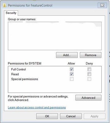
1. Once the locked keyword is identified, use "regedit.exe" to locate the keyword in and then, rightclick and select "permissions" to open the “permissions” window.


2. In the opened permission window, click “Add” button in the “group and username” section if there is no name in the block and the following screen should appear.


3. Selecting the “Advance” button to open up the following screen.


4. Click “Find Name” button to add “SYSTEM” as the username.


5. Click "OK" to return to the 1st opened permission window.
Note that the checkboxes in the "Full control" and "Read" cannot be set until one has reclaimed the ownership of the keyword.
6. To reclaim ownership, click "Advance" and in the next window, select “owner” tab and then change the owner’s name to reclaim ownership of the keyword.


6. Return to 1st opened permission window and click “Full control” check box.

7. Click “OK” button and then test if one can open the keyword in the registry editor.

Quicker Way to Unlock?

Instead of unlocking the keywords one by one, one can release all the locks in the sub keyname under the keyname “FeatureControl” by releasing the lock in the “FeatureControl” keyword. To do so, one must click the checkbox "Replace owner in subcontainer and object" when reclaiming the ownership of the keynames. Repeat same for the "permission" tab.

Wednesday, December 15, 2010

Repair Spin Mop or Magic Mop

14 December 2010

IntroductionMagic mop or 360 degree mop are spin mops. The earlier model has a foot pedal with gearing system that will spin the cage as the pedal is being “pumped”. This article will describe how to repair this kind of spin mop.


How Spin Mop works?The spin mop has a set of gearing system. When the pedal is stepped on, it will spin the centrifugal cage. The heart of the system is a “one way bearing” that allow the force to be transmit to the shaft of the centrifugal cage.

This bearing has about 8 small little needle bearings in it that are arranged to “lock” the gear to the shaft whenever a force is applied to turn the gear. As soon as the force is removed or when one stops the pedal “pumping”, the needle bearings will “unlock” themselves, allowing the centrifugal cage to continue spinning freely with the “one way bearing” now acting as a normal bearing. The animation of the “one way bearing” can be found here


What Can Go Wrong?
After some use, these little needle bearings will wear out and no longer able to “lock” the gearing system to the shaft of the centrifugal cage. The centrifugal cage will stop spinning.

What can be done?a) Dismantle the gearing mechanism

1. Unscrew the 4 screws that attach the gearing block from the pail


2. Remove the small pinion gear that is attached to the shaft


3. Remove the "one way bearing" by knocking the old one out


4. Replace the “one way bearing”. Check to rotate the shaft by hand to ensure the correct direction of the bearing before inserting the bearing. The “one way bearing” will not work if it is inserted in the wrong direction.  It may be necessary to put the bearing back on to the shaft to test the rotation just to be sure.
5. Re-assemble the gearing block.

After Note:

How to remove the Bearing from its Housing

First remove as many old bearing needles from the housing using a small watch screw driver as shown


then put the gear over the vice with a gap that will allow the old bearing to be knock out lightly  using a small screw driver and a hammer,  aiming at the rim of the bearing housing space left over by the needle bearings.   When the bearing is on its way out,  grip it by the vice.  A twisting motion will remove the bearing.


Saturday, December 11, 2010

How to Sharpen a Knife or Chopper

10 December 2010

Introduction
There are tons of articles and videos on the web telling people how to sharpen a knife or a chopper. Some are shown by professional chef. However, none could help a layman sharpening a knife or a chopper properly

Why?
The secret of sharpening a knife is to have the knife always maintaining at a constant angle of about 20 degree to the surface of the sharpening stone or sand paper when sharpening a knife. If the knife edge is irregular, the knife will never be sharp.

How?
To maintain a constant angle, one can use something like a thicker steel ruler to provide a shim or a spacer to “wedge” the knife at about 20 degree angle to the surface of the stone. The trick is on how to stick the ruler to the knife while sharpening the knife.

A Simple Method
a) Find a piece of PVC electrical trunking about the length of the knife. One may be able to get one free from the electricians as they often have some waste piece lying around in the work places; the PVC trunking will usually have a "tongue and groove" arrangement to snap the cover in place;


b) Remove the cover of the PVC trunking which should have a “groove” in it. Cut the “groove” piece out of the cover and snap the piece to the knife as shown.


c) Start sharpening and one will always have a knife or a chopper sharpened in a professional way.

Wednesday, December 8, 2010

How to Sharpen a Planer Blade

8 November 2010

Introduction
There are many ways to sharpen a planer blade instead of replacing and throwing them away. This article will introduce one easy way.

The Planer and Planer Blades
The planer used is as shown. It has 2 blades, each has a length of 3-1/4" and are made of HSS steel.


When the blades are blunt, it will not give a good cutting surface on the wood and the surface will have a fluffy feeling.
The Sharpening Tools
The usual way to sharpen the blade is to use a standard blade sharpening tool which has adjusting screws for angle and other adjustments. Grinding stones are often used. The sharpening work will require some professional skill to prepare grinding stones etc. This article will introduce a simple and yet effective way for DIYs using tools that can be made in just less than ½ hour. No professional skill really required.

The Materials
a) A base made from a piece of plywood measuring around 100 mm x 75 mm ( 4” x 3”) or with the width to suit the length of the blade;
b) A 15 mm PVC tube of about 75 mm (3”) in length;
c) 4 wood screws and washers; 2 shorter ones to tighten the blade to the base and 2 longer ones to tighten to the base to a PVC tube for adjustment of the blade angle;
d) 2 pieces of water base sand papers; one of 240 grade and the other of 300 grade or finer
e) Optional: a set of rollers to be mounted underneath the 15 mm PVC tube so that the base can slide freely on the sand papers. One can use the small rollers that is stripped from the spoilt computer mouse for this purpose.

Other tools required are electric drills and suitable drill bits

The Set Up
a) Drill 2 rows of holes and 2 small holes as shown on the base
b) Drill 2 small holes on the PVC tube to hold the longer screws


The Completed Assembly


Note:
1. One can omit having rollers mounting beneath the PVC if one can always place the PVC tube outside the sand paper area. Anyway, PVC tube are replaceable if they are worn.
2. Constantly check the grinding surface of the blade and adjust the angle of the blade to be grinded. When the angle is correct, make a marking on the PVC tube and the base.
3. When the blade is ready, one should feel the blurs on the opposite edge of the blade. Dismantle the blade and grind away the blur on a fine sand paper. To ensure the blade is always placed at a small angle to the sand paper, one can use a steel ruler or the back of another sand paper to "jack" up the opposite end of the blade when grinding away the blurs.

Thursday, October 7, 2010

Access Denied in Windows 7 Registry

Introduction

Windows 7 is fast and easy to use but many users said they had tried and went back to XP. They said Windows 7 was not stable. Some complained about program not able to run or run slower than XP after some usages. Reinstallation of these programs often failed. This article will describe a way to solve some of these problems.

Why?

One of the problems is the denial of access to change certain keys required by the programs in the Registry. After some period, the ownership or the permission of the Registry key will be changed for some reasons, probably caused by User Account Control (UAC). The programs will lose the privilege to access and change these keys under normal operation. The solution is to restore the ownership and permission of these keys.

How ?

a) Prepare to check which key was denied the access.

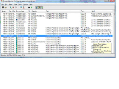
To monitor the Registry, download Process Monitor . Install and run.


3. To limit the number of events to be display, in the “Filter” menu, select “Filter”
4. In the Architecture dropdown box, select “Result” and type in “ACCESS DENIED” in the box as shown


5. Click ok. The monitor is now ready to capture any access denial events for study.

b) Run the faulty application or installation or any program again. this time, check if there are Registry keys being denied access. Note down this key and use “Regedit” to reclaim ownership or permission to change these keys.

What if there are plenty of Registry to Change?

When there is a lot of keys to reclaim ownership or permission, it may be necessary to reset the entire Registry to the defaulted ownership or permission.

How ?

Important Notes: It is advisable to backup by exporting the entire Registry or otherwise save in another disk or partition. The reset of ownership or permission by SubInACL can upset some programs.

1. Download SubInACL which is a program that will enable administrators to manage files, registry keys, and services.

2. Unzip and run SubInACL. It will create a new folder called “Windows Resource Kits/Tools” inside the Program Files (x86) folder.

3. Start up “NotePad”. Copy and paste the following

subinacl /subkeyreg HKEY_LOCAL_MACHINE /grant=administrators=f
subinacl /subkeyreg HKEY_CURRENT_USER /grant=administrators=f
subinacl /subkeyreg HKEY_CLASSES_ROOT /grant=administrators=f
subinacl /subdirectories %SystemDrive% /grant=administrators=f
subinacl /subkeyreg HKEY_LOCAL_MACHINE /grant=system=f
subinacl /subkeyreg HKEY_CURRENT_USER /grant=system=f
subinacl /subkeyreg HKEY_CLASSES_ROOT /grant=system=f
subinacl /subdirectories %SystemDrive% /grant=system=f

4. Save NotePad file as “Reset.cmd” in the “Windows Resource Kits/tools” folder.

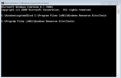
5. In the box of the Windows Startup Button, enter “cmd” (without quotes) and rightclick “cmd.exe” when the file appears at the top of the window and select to run as Administor.

6. Type “cd C:\Program Files (x86)\Windows Resource Kits\Tools” at the prompt, follow by “reset.cmd”


7. The program will run for the next 3 minutes to change all the ownership and permission of the entire keys in the Registry to the default value

Tuesday, August 24, 2010

The Tokyo Tunnel - G-Cans

24 August 2010

Introduction
The Tokyo flood tunnels – G-Cans project started construction in 1992 and completed in 2004, about 12 years later. It was just in time to be tested in tyhoon 22 in 2004 when 14 families were reported to be affected instead of 236 families before the completion of the project. The tunnel collects water from Tokyo downtown district and discharge it into the Edogawa river.


The Tunnel
The tunnel is 10m in diameter and about 6.3 kilometers (four miles) long. It is buried 50 metre under the ground in the Tokyo suburbs.

It has 5 concrete silos, each having a diameter of about 32 metres and is about 70 metres tall.

The tunnel is connected to a gigantic water tank measuring about 78m width, 177m long and 25m tall (or 350,000 m3). The tank is propped by 59 numbers of gigantic pillar, each weighing about 500 tons. As the pillars look like those in ancient temples, some named this water tank “the underground temple of Tokyo”.

Connected to this water tank are series of water pump that have a total output of 14,000 hp or 10 MW. They can discharge flood water up to 200 m3 per second or one Olympic pool water in 10 seconds.

The Cost
Estimated to be about US 2.0 billion

The Volume
The tunnel can hold approximately 640,000 m3 of flood water.


iPhone and iPad: How to Create a Short Cut in Home Screen to Clear Cache & History

23 November 2024 What are Cache and History? Cache and browser history store information about websites you've visited.  The C ache s to...