Search This Blog

Saturday, March 5, 2022

Reviving ASUS eee901 NetBook PC for Data Scrappings

5 March 2022

# eee901, Network, SSD upgrade,  mSATA,  mini-PCIe,  Windows

This ASUS eee901 was a very popular netbook PC about 10 to 15 years ago.  It was one of the cheap netbook PC that uses SSDs for memory storage.   It was very hackable and many hobbyists like to do all sorts of modification work using this PC.  

Because the netbook uses only 5 Watts.  I bought a couple of these for stock data mining which required the PC to be operating 24/7.  When the SDD finally failed to work and plenty of free stock screening websites are available free for downloading,  I decided to retire them some 5 years.

Lately,  I took up the interest to do stock data mining again. This time is for data that are not available anywhere on the Internet.   The choice then was between buying a new netbook or upgrading the eee901 with a faster and bigger SSD.

What SSD Were Used?

These ASUS netbooks use a special SSD called mini-PCIe SSD.  These SSD has a similar form factor as the mini-SATA (mSATA) SSD.  Mini-PCI SSD is not easily available and mSATA SSD cannot be used to replace Mini-SSD directly in the ASUS netbook.

The Final Choice

.I decided to revive the eee901 for the following reasons

1)  Netbook has now been replaced by the tablets which run on either Android or iOS.  They are not good for running the Excel macros which were written earlier for data mining;

2)  There are adaptors available to convert mSATA SSD to mini-PCI SDD for use in eee901.  The adaptors are fairly cheap.   The SSD replacement and upgrading work is estimated to cost less than SGD$30/=. It is much cheaper than a new netbook;  moreover,  I have a few spare mSATA SSD lying around and I can use them for the upgrading work.

The only Snag

The eee901 PC has two SSD;  one 8GB master SSD that is accessible after removing the cover;  the other is the 4GB slave SSD that is hidden inside the PC.   When the new adaptor SSD is used to replace the 8GB Master SSD,  the PC will recognise only the new adaptor SSD as a slave.  The BIOS will always give this warning error about "master SSD not found" whenever the PC is booted up.  The warning error cannot be defeated because it is an error message.   It will stop loading up the Windows.  This is not good when one is trying to automate the PC to start up windows and run the excel macros automatically.   

Installing the adaptor SSD to replace the hidden 4GB will solve this startup error but the adaptor SSD must be shortened because the hidden 4GB is half-height.  It is around 50 mm long whereas the new adaptor SSD is around 70 mm long. 

Can the Adaptor SSD Be Shortened?

Yes,  it can.  One must use 1/2 height mSATA with a short piece of PVC plastic added as shown in this automated picture.  There is just enough room in eee 901 for the installation of this new and shortened adaptor SSD


How to Install the Inside the eee901?

Here is one of the video


Enhanced Performance

Users will find the replacement Adaptor SSD running much faster than the original SSD.  This is because the mSATA is of the more advanced Technolgy.  The mSATA's speed can be several times that of the original SSD.  

With the larger capacity SSD,  one can use the original Windows 7 with the response and speed,  at times,  even better than the Intel E8400 PC with the hard drive.  Some has tested eee901 using Windows 10 but the response was a bit sluggish as reported because Windows 10 will require 3 GB RAM to run efficiently.  The eee901 only has a maximum RAM of 2 GB.

Sunday, February 20, 2022

DIY Protective Covers for Continuous Glucose Monitoring (CGM) Sensors


19 February 2022

About 1 in 10 people will have diabetes. This number of diabetes is expected to double in future years.  It is a serious disease that will cause death if it is not properly managed and controlled.  The disease is more commonly found in aged people.   People get diabetes when their blood glucose is too high.  This glucose in the blood is commonly referred to as blood sugar, 

This article will not go into details about controlling and managing blood sugar as there are lots of good articles written about this on the net.   I just want to share about how to DIY a  cover for the Continuous Glucose Monitoring (CGM) Sensors when one happens to wear one.

What is Continuous Glucose Monitoring (CGM)?

There are generally 2 common types of methods to measure the level of blood sugar at home.  One of them is by using a glucose meter with a special test strip;  


the other is by using a special sensor that has to be planted on our body.   


The former is most commonly found at home and have been used for years.   The latter is only available in recent years.  It is by far the most effective way to control and manage the blood sugar in our bodies.  More details about CGM can be found here and elsewhere on the net.   This article will only talk about how to best secure and how to DIY a cover for the  CGM Sensor when it is installed on our body.

Why the need to secure the Sensor?

Usually,  the sensors are provided with means to secure the sensor to our body as one can see in the above picture,  But it does not look really very secure.  It is not that it will fall off that easily;  it is just the feeling of most people who wear them that the sensor could just "shear off" when it hit against something like a door jamb.  Besides,  there is always this sensation of arm-sore that will not go away even after days of wearing the sensor.  This could be because the needle of the sensor could be moving around when one is flexing the arms.  

As such,  one can find a lot of companies selling specially made covers or patches to secure these sensors.  They are not cheap either.


How to DIY the Cover?

There is actually no requirement specified by the manufacturer nor there are any standards available for the design of the sensor cover.   It is generally felt that the cover should have the prerequisites:

a)  It is waterproof;

b)  It must have a strong adhesive to stick firmly.  Easily replaced.

c)  It must not cause skin occlusion 

It must be waterproof so that water will not soak the sensor or its adhesive base when one is taking a bath.  It must have a strong adhesive itself to stick firmly to the skin & easily replaced.    Most important of all,  it must not cause skin occlusion which will often cause skin irritation,  leading to skin rashes or inflammation.  

Searching around,  we found the 3M micropore tape or similar most suitable for the DIY as it fit the 3 prerequisites.  The 3 M tape comes in 4 sizes,  the 3",  the 2",  the 1" and the 1/2".  The most common one found in the self is the 2",  the 1" and the 1/2";  but,  the most suitable one for use as a cover for the sensor is the 3" type.    

How to Use the Smaller size 3M Tape?

The only way is to join the pieces together using the following step by step.  In this case,  the most suitable one is the 1" type.

1)  Cut 3 pieces of 1" tape;  each tape is best to be roughly about 3.5 in length;

2)  Laid the tape on the glass.  In this example,  a mobile phone was used;


3)  Lightly place the 3 pieces of tape,  overlapping the edges as shown attached.   Apply some pressure over the overlapping edges to stick the pieces together;


4)  After that,  remove the tape;

5)  Cut a small round piece of plastic using a small bottle as the template as shown as stick the round piece right in the centre.  the plastic round piece should be larger than the adhesive of the CGM sensor.  This is to ensure the tape will not stick to the sensor and the adhesive and the tape can be easily replaced if necessary;


6)  Trim the DIY sensor cover and place the cover over the sensor as shown.


Thursday, February 3, 2022

How Best to Test & Calibrate a Blood Pressure Meter?

3 February 2022

A blood pressure meter is a common household item nowadays.  This is especially so when there are elderly people in the house.  

In the old day,  we used to have a mercury type of pressure meter which they called "sphygmomanometer".


Today,  most of us will use an electronic type of blood pressure meter as shown below
The good old mercury type of pressure meters are still being used by a lot of medical personnel because it is still the most reliable and accurate pressure meter around; whereas, electronic meters will often need regular calibration and routine checking.

This article will show how one can accurately check the accuracy of an electronic meter.


What's Needed?


How to Connect up?

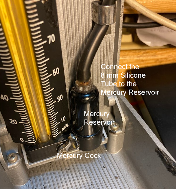
 1.  Connect 8-mm Silicone Tube to the mercury reservoir as shown


2.  Connection the 8-mm tube to the T-Joint


Testing 

As shown in the video,   this Omron Blood Pressure BP742 meter under test has an accuracy of about +4 mm Hg or 3% of reading @ 131 mm Hg.  it is slightly off the manufacturer's limits of +- 3 mm Hg or 2% reading.  However, it has an accuracy of -1 mm Hg or -1% of reading @ 100 mm Hg which is better than the manufacturer's limits.

Diastolic &  Systolic Pressure Readings

To complete the test,  one should also place a stethoscope underneath the handcuff to listen to the heartbeats to check the accuracy of the systolic and diastolic pressure..  

During the working process,  one can hear the meter pumping up the pressure to the handcuff and the heartbeat sounds through the stethoscope as the pressure is building up.  When the pressure goes higher than a certain set of systolic pressure,   the meter will stop pumping.  This is when one could not hear any heartbeats.  Thereafter,  the meter will slowly release the pressure and the pressure readings will drop.  Note down the reading when one first hears a heartbeat. This is systolic pressure.  With further pressure drop,  note the reading when one no longer hear the heartbeat sounds. This is your diastolic pressure.  Compare this two readings with the readings recorded by the meter.  They should be within +-3%.

Calibration

Unfortunately,  there is no adjustment allowed in this Omron Blood Pressure BP742 meter as shown in the following picture.  It would appear the calibration has to be carried out by using some kind of software and this can be done only by the manufacturer as explained by the author of this article...


How Much is a Sphygmomanometer?

The market is selling a Sphygmomanometer at a price of around SGD 40/= to about SGD 300/=.


Monday, January 24, 2022

Repairing Philips Electric Shaver Model C644


24 January 2022

This Phillips Shaver was found not working.   The blade will move but if one starts to cut the hairs,  the cutting blade will stop moving.  One can still hear the motor spinning in the background.   If one removes the blade from the unit,  one can see that the blade rotator will spin but it will stop if one tries to use one's finger to stop the rotator from spinning.   


Why?

The blade rotator is slipping.    It is not "catching" firmly onto the rotor of the motor.   The rotor catch must be loose.   This article will recommend a fix.


Disassembling

1.  Removing the Blade holder

The blade holder which is in the form of metal clips must first be removed.  To remove the clips,  one must use a small screwdriver to free the top catch from the 2 catch holders as shown in the attached picture. 


2.  Remove Motor Chamber's Top Cover

Once the blade holder is removed,  one can easily remove the motor chamber's top cover by prying open its bottom using a small screwdriver.  The cover is shown in the following picture.    


3.  Remove the Sliding Adjuster Assembly

Next is to remove the sliding adjuster and the slider ring as shown.  

When removing the slider ring,  watch out for the spring-loaded plunger underneath the ring.  Make sure the plunger won't spring out.   If the plunger is lost and missing, the sliding adjuster will not work properly.


4.  Remove the Switch Cover

Once the slider ring is out of place,  one can start to remove the top cover or the switch cover from the shaver by using a small screwdriver to pry open the cover,  starting from the bottom and working the way to the top until the cover is completely removed.


The Parts


Why Blade Rotator is Loose?

There was no screw or other means to secure the rotator to the motor's rotor.  It is suspected that there is a "catch" built into the rotator because one can feel the "click" when one inserts the rotator back onto the rotor.   

The "catch" must have failed to catch firmly onto the rotor because the rotator was found to be quite oily.  In this case,  the owner must have overlubricated, sprayed too much WD40 or otherwise and accidentally allowed the lubricants to get into the rotator. This must have caused the rotator to fail to "catch" onto the rotor.   The slipping of the rotator will occur when the blade met some resistance.   

Knowing this to be the problem,  cleaning up and soaking the rotator in solvents such as thinner or acetone solved the problem.


What if the Rotator still Slips?

One will have to replace the blade rotator if one can find the spare part;  if not,  the only alternative is either to "stuff" in between the rotator and the rotor with a tiny strain of small electric wire.  The other way is to permanently fix the rotator to the rotor using superglue.  The use of superglue should be the last resort.

Reassembling

To reassemble back the shaver,  reverse the disassembling steps.

Saturday, January 22, 2022

How To Assemble a PC? (Lesson No 3)

 21 January 2022

In this lesson,   we will install the motherboard and other PC components.  Take this motherboard as an example.  


The motherboard is made by Gigabyte and the model number is as shown which is GA-H61M-S2p.  It has the following built-in

1.  4 SATA 3 Gb/s output ports for disk drives and DVD ROM;
2.  8 USB 2.0/1.1 ports (4 ports on the back panel, 4 ports for front panel)
3.  1 Ethernet LAN Port
4.  1 VGA Port (D-Sub port)
5.  4 Expansion Port ( 1 PCIex16 for graphic card, 2 PCIex8 and 1 PCIex4 port for other cards
6.  1 x PS/2 keyboard port & 1 x PS/2 mouse port
7.  3 x audio jacks (Line In/Line Out/Microphone)


To install,  one would need to go to the motherboard webpage to download the following

1.  The User's Manual

2.  The following Drivers

a. Realtek HD Audio Driver

b.  Intel Management Engine Interface

c.  Intel Management Engine Interface

d.  Realtek LAN Driver

e.  Intel® Rapid Storage Technology

f.  Intel SATA Preinstall driver

g.  Intel VGA Driver (for Ivy Bridge CPU)

The manual will be required for the installation of the various casing connector to the motherboard.  The drivers will be required after one has installed the Windows operating system.  Without these drivers,  the windows will use the standard driver which might not give optimum performance.   One would need to select the OS to download the correct type of drivers.    

There are several versions of the windows operating system.  The latest one is Windows 11.    The more common ones are Windows 10 and Windows 7.    Windows 7 is no longer supported by Microsoft.  One can still install and use it.  

As this is an old motherboard,  it has no drivers for Windows 10 or Windows 11 listed on the manufacturer's webpage.    For those who prefer to install the Windows 10 or Windows 11 operating system on this PC,  they would first have to use the drivers for Windows 7 first.  Windows will install the drivers if they are usable;   if not,  the new ones will be installed automatically when one do a windows update after the PC has been set up and running.  

Physical Installation

A) Motherboard Installation

1. First, install the Power supply Unit if it has not been already fixed onto the casing;

2. Then,  one will need to install the backplate;   after that,  the motherboard. 


The motherboard will have 6 screws to secure it firmly to the casing.   Once the motherboard has been installed,  one can start to plug in all the cable connectors.

The cable connectors are all "keyed" in such a way as to avoid any wrong connections.  The only connectors one would have to watch out for are those Front Panel USB and casing connectors.   One will need the User's Manual to connect up these 2 connectors properly.

1)  Front panel USB Connector

These connectors are often supplied with individual connectors,  one for each cable.  There are 10 pins for each USB connector. Each set of pins can connect 2 USB ports.   One will have to identify and install the cables properly according to the diagram.  The wrong connection could cause problems and may even spoil the USB devices or motherboard. 


2)  Front Panel Casing Connectors


Similar to the front panel USB connection,  the wiring might come in a different combination.  One will need to identify which cable will be going to which pin.  The cables are always marked according to function;  for example,  Power LED,  etc.

B)  Hard Drive Installation

Here is a tutorial video for the installation of the hard drives


C)  Windows Operating System

Here is an example of how Windows10 can be installed free


Thursday, January 20, 2022

What could have caused UK to Remove Face mask rules and other Covid Control Measures?

20 January 2022

The UK's Prime Minister, Mr Borris Johnson, said that face-covering in public places and Covid passports will not be mandatory in England from next Thursday or from 27 January 2022.


The UK's Prime Minister also said the government would immediately drop its advice for people to work from home.

He said the scientists believed the Covid wave had peaked in England.  They said they have done an infection survey recently.

What's the Situation in the UK Today?


The UK has a population of about 67 million.   The COVID-19 pandemic had a major impact on the UK in 2020 and 2021. 


Here are  some statistics about Covid-19 in the UK


1)  Confirmed cases


There were 108,069 new cases on 19 January 2022, and 652,469 people in the last 7 days. This shows a decrease of 386,031 compared to the previous 7 days.


2)  Death

There were 359 new deaths within 28 days of a positive test for coronavirus reported on 19 January 2022, and 1,865 people in the last 7 days. This shows an increase of 141 compared to the previous 7 days.


3)  Admission to Hospital

There were 1,752 new hospital admission on 15 January 2022, and 14,927 people in the last 7 days. This shows a decrease of 770 compared to the previous 7 days.


How do these compare?

The UK's infection rate has begun to reduce about 2 weeks ago.  But this rate is not that low when compared to other selected countries which were attacked by Covid in 2020 as shown in the following chart. The chart shows that UK's 7-day rolling average rate is now about 1,500 infections per million people lately.  This is about 50% down from the peak of about 1,600 infections per million on 5 January.   


As for the death rate,  UK's death rate has increased 4 times.   It is not low either when compared to other countries.   The death rate was 1.08 per million people on December 29.   It was about 4.0  on 18 January 2022 as shown in the following chart.


Now,  what made the UK Government thinks that the Covid situation will not be serious and why did they suddenly relax its Covid control measures?

Why?   

The one reason that we can justify the UK's view is that Covid is no longer considered to be a serious and life-threatening disease as compared to other diseases in the country.  

If we study the following chart carefully,  we will find that the UK has the lowest "Excess Mortality rate" among the selected countries.  This rate is about 100% lesser than what they have gone through in early 2020 when the rate was about 107% as shown in the following chart.  

Then, the UK could have experienced the worse,  and the present excess mortality rate of 5% is nothing compared to those dreadful days.   This is like one has seen the big devil before,  one is no longer afraid of the smaller devil which is "100%" smaller.


What about the Covid Case Fatality Rates (CFR)?

The UK presently also has the lowest case fatality rates (CFR) compared to other countries.  The case fatality rate measures the number of deaths against the Covid Infection cases.   If CFR is low and the infection is still high,  people would be lesser worried about the spread of the disease.


Conclusion

The UK will be taking a very bold step forward.  They assumed that Covid is no longer as dangerous as it used to be;  also,  it is not more serious than other diseases now prevailing in the country.  

Quite sure many countries will be watching closely what will happen in the UK in the future;  they might want to follow suit if the UK's did not experience any conditions worse than before.

Update:  21 January 2022

Estimating the % of  Immunity 


Sunday, January 16, 2022

How to Assemble a PC? (Lesson No 2)

 15 January 2022

In lesson 1,  we listed and showed the various components to be used to assemble a PC.  If we have already in our hands all the required components,  we can start assembling them together.    Lesson 2 will show how we could do that.  

The PC Casing

The casing is usually made of metal.   It has side panels that can be opened to fix the components such as motherboard, hard disk and other peripheral cards such as video cards etc.  It has also a casing fan for additional cooling.  There are also a bunch of wires for connection to the front panel control switches such as the on/off and reset switches, etc.  Here are the pictures of where are these wires and where one can install what PC components

a)  The Casing

Front and Back


Inside


Step By Step

1.  Installing Power Supply

The power supply has 4 screws for mounting to the casing.  It has 5 bunches of wires for various components as shown in the picture.  They must be connected to the respective sockets of the components.  The connectors are usually "keyed" such that there should be no wrong connection problem to be expected.


The close up view of the 5 types of power supply connection is as shown


2)  Installing the CPU 

If the motherboard has not been installed,  it will be much easier to install the CPU when the motherboard is outside the casing

Here is a good video on how the CPU could be fixed onto the Motherboard.   Note that there is always a dummy CPU or some sort of protection to prevent accidentally damage of the very delicate and flimsy pins located inside the CPU socket.  Any bent pins in the CPU socket will make the motherboard unusable. 

3)  Installing the motherboard

The motherboard usually have about 6 to 7 screw holes for mounting to the casing,  some of which has been marked in this motherboard.  The picture shown below has been labelled to show where the various PC components should be installed.  It would be good to check the manufacturer's manual to find out how to install the motherboard as different motherboards might have different installation requirements. 


To be continue

iPhone and iPad: How to Create a Short Cut in Home Screen to Clear Cache & History

23 November 2024 What are Cache and History? Cache and browser history store information about websites you've visited.  The C ache s to...